GE
RFQ Ready
GE IS200VVIBH1CAC Vibration Monitoring Module – Mark VI
Mark VI
Origin US
Vibration Monitoring Module
Request verified availability, condition, replacement risk review, packing options and courier lead time for IS200TRLYH1BED IS200TRLYH1B.
Click Request Quote and the part number is inserted into the inquiry form automatically.
Core fields for model confirmation and RFQ routing. Detailed product narrative remains below.
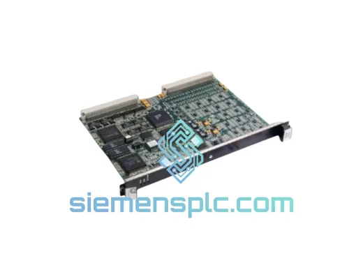
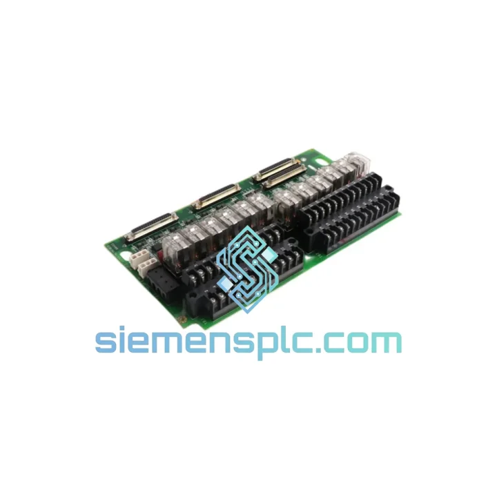
The IS200TRLYH1BED is a relay terminal board engineered for the General Electric Mark VI turbine control platform. Its primary function within the control loop is to serve as the hardwired discrete output interface between the Mark VI controller backplane and field-side actuators — including solenoid valves, motor starters, and trip relay coils. Unlike software-configurable I/O modules that rely on firmware abstraction, this board operates at the physical layer: relay contacts close or open in direct response to drive signals from the VCMI or VCRC controller cards, with no intermediate logic layer that could introduce latency or ambiguity in safety-critical switching events.
In a turbine protection architecture, deterministic output switching is non-negotiable. The IS200TRLYH1BED achieves this through electromechanical relay elements rated for industrial duty cycles, with contact configurations that support both normally-open and normally-closed wiring topologies. This dual-topology capability allows engineers to implement fail-safe de-energize-to-trip logic without external relay interposing, reducing component count in the field junction box and eliminating one potential failure node from the protection chain.
📧 Real-time Stock & RFQ: [email protected] | WhatsApp: +86 18359268345
| Parameter | Specification |
|---|---|
| Manufacturer | General Electric (GE) |
| Part Number | IS200TRLYH1BED |
| Alternate P/N | IS200TRLYH1B |
| Module Classification | Relay Terminal Board |
| Compatible Platform | GE Mark VI Turbine Control System |
| Board Series | IS200 I/O Terminal Family |
| Output Type | Electromechanical relay, dry contact |
| Contact Configuration | SPDT (Form C) — NO / NC selectable per field wiring |
| Rated Contact Voltage | 250 V AC / 30 V DC |
| Rated Contact Current | 5 A resistive load |
| Coil Drive Signal | 24 V DC nominal from VCMI/VCRC backplane |
| Isolation | Optical isolation between logic-side drive and relay coil stage |
| Operating Temperature | 0 °C to +60 °C (storage: −40 °C to +85 °C) |
| Humidity | 5% to 95% RH, non-condensing |
| Mechanical Form Factor | PCB terminal board, DIN-rail compatible mounting bracket |
| Connector Interface | Screw-terminal field wiring blocks; ribbon cable to controller card |
| Weight | Approx. 1,420 g (assembled with terminal hardware) |
| Warranty | 12 months — functional defect coverage, replacement or refund |
The IS200TRLYH1BED implements a two-stage signal path between the Mark VI controller and the field load. Stage one is the logic-side drive circuit: the VCMI or VCRC card asserts a 24 V DC coil drive signal through a dedicated backplane connector. This signal passes through an optocoupler isolation barrier — a phototransistor-LED pair rated for a minimum 1,500 V RMS isolation voltage — before reaching the relay coil driver transistor. The optocoupler stage serves two functions simultaneously: it galvanically separates the controller’s logic ground from the field-side relay circuit, and it provides a defined switching threshold that rejects noise transients below approximately 3 V, preventing spurious relay actuation from backplane-coupled interference.
Stage two is the relay switching element itself. The electromechanical relay used in this board class is selected for low contact resistance (typically <100 mΩ at rated current) and high mechanical endurance — rated contact life exceeds 10 million operations under resistive load conditions. For inductive loads such as solenoid valve coils, the board incorporates transient suppression diodes across the relay coil and, in some board revisions, metal oxide varistors (MOVs) across the output terminals to clamp inductive kickback below the relay contact’s rated transient voltage.
EMC performance is addressed at the PCB layout level. The relay coil drive traces are routed with ground plane shielding on adjacent copper layers, reducing radiated emissions from the switching transient. The terminal block layout physically separates the 24 V DC logic wiring from the AC field wiring, enforcing a minimum creepage distance compliant with IEC 60664-1 for Pollution Degree 2 environments — relevant in turbine enclosures where oil mist and particulate contamination are operational realities.
The board does not contain onboard firmware or EEPROM. Its logic is entirely deterministic and hardware-defined, which means there is no firmware version dependency, no configuration file to manage, and no risk of a software update altering output behavior. This characteristic is particularly valued in safety instrumented system (SIS) applications where proof-test intervals and functional safety documentation require a stable, auditable hardware baseline.
Every IS200TRLYH1BED unit supplied through siemensplc.com undergoes a structured pre-shipment verification sequence. Visual inspection confirms label integrity, PCB surface condition, and terminal block completeness. Electrical bench testing verifies relay coil resistance within the manufacturer’s specified tolerance band and confirms contact continuity and isolation resistance between the logic-side and field-side circuits. Units that do not meet these parameters are quarantined and not dispatched.
Packaging follows anti-static and mechanical protection protocols: boards are placed in conductive foam-lined anti-static bags, sealed, and packed in double-wall corrugated cartons with void fill rated for international air freight handling. Each shipment includes a packing list, commercial invoice, certificate of origin, and the pre-shipment test record.
Dispatch is from Xiamen, China. Standard export transit times via DHL Express or FedEx International Priority are 3–5 business days to Southeast Asia, 4–6 days to the Middle East and Europe, and 5–7 days to North America. For bulk procurement, sea freight LCL and FCL options are available with full export documentation including HS code classification and customs value declaration. All exports comply with applicable Chinese export administration regulations and destination country import requirements.
📧 Email: [email protected]
📱 WhatsApp: +86 18359268345
🌐 Web: siemensplc.com
📍 Location: Xiamen, China
© 2026 siemensplc.com. All rights reserved.
We check the full part number, brand, series and visible nameplate information before quotation.
Sales confirms stock path, condition option, quantity and realistic lead time for export dispatch.
DHL, FedEx, UPS or buyer courier arrangements can be reviewed with packing requirements.
Similar brand or category products for fast comparison and multi-item RFQ lists.