KUKA
In Stock OK
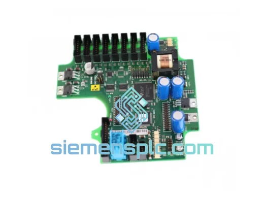
KUKA 00-107-264 Teach Pendant – KCP2 Series
Request verified availability, condition, replacement risk review, packing options and courier lead time for 00-107-264.
BrandKUKA
Part Number00-107-264
ConditionAvailability Check
Lead TimeRFQ Confirmation
DocumentsDatasheet / photos by RFQ
ShippingExport packing available
Auto-filled RFQ
00-107-264
Click Request Quote and the part number is inserted into the inquiry form automatically.
- Reply by email: [email protected]
- WhatsApp / Tel: +86 18359268345
- Mon-Sat 9:00-18:00 GMT+8
Procurement Data
Key Product Information
Core fields for model confirmation and RFQ routing. Detailed product narrative remains below.
- Brand
- KUKA
- Primary Part Number
- 00-107-264
- Product Type
- Teach Pendant
- Product Family
- Other series
- Manufacturer
- KUKA Roboter GmbH, Augsburg, Germany
- Country of Origin
- DE
- Catalog Category
- Robotics & Motion
- Operating Temp.
- 0 °C to +50 °C
- Warranty
- 12 months from date of shipment
Model confirmed for inquiry
00-107-264
Send quantity, destination and urgency. The RFQ form keeps this part number attached.
Request Quote
Product Overview
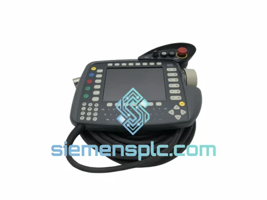
KUKA 00-107-264 KCP2 Teach Pendant: Operator Interface Architecture for KR C2 Robot Control Systems
The KUKA 00-107-264, commercially designated as the KCP2 (KUKA Control Panel 2), is the primary human-machine interface unit engineered for the KUKA KR C2 robot controller platform. Within a KR C2-based workcell, the KCP2 serves as the sole certified operator terminal through which motion programs are created, edited, executed, and monitored. Its role in the control loop is not peripheral — the pendant is the physical boundary between the operator’s intent and the robot’s motion execution layer, with hardware-enforced safety interlocks that cannot be bypassed by software alone.
The unit communicates with the KR C2 cabinet via a proprietary 15-pin D-sub pendant bus, carrying both data and power over a single shielded cable assembly. This bus architecture serializes all pendant I/O — display refresh, keypad scan, enabling switch state, and E-stop status — into a deterministic communication frame that the KR C2’s real-time kernel polls at a fixed cycle rate. Any interruption or frame error on this bus triggers an immediate Category 0 stop, consistent with IEC 62061 SIL 2 requirements for safety-related control systems.
Real-time Stock & RFQ: [email protected] | WhatsApp: +86 18359268345
Technical Parameters
| Parameter | Specification |
|---|---|
| Part Number | 00-107-264 (alt: 00-226-429) |
| Series | KCP2 — KUKA Control Panel 2 |
| Compatible Controller | KUKA KR C2, KR C2 ed05 |
| Communication Interface | Proprietary KUKA pendant bus, 15-pin D-sub |
| Display | Color LCD, 640 × 480 px (VGA), touchscreen |
| Keypad | Membrane-type, 64-key layout with function keys |
| Emergency Stop | Dual-channel hardware E-stop, Category 0, IEC 60204-1 |
| Enabling Device | 3-position enabling switch (off / enable / panic), ISO 10218-1 |
| Operating Voltage | 24 V DC (supplied via pendant cable from KR C2 cabinet) |
| Power Consumption | ≤ 15 W |
| Cable Length (standard) | 10 m; custom lengths available on request |
| Operating Temperature | 0 °C to +50 °C |
| Storage Temperature | −25 °C to +70 °C |
| Relative Humidity | 5 % to 95 %, non-condensing |
| Protection Rating | IP 54 (IEC 60529) |
| Weight | Approx. 500 g (without cable) |
| Dimensions (H × W × D) | Approx. 310 × 210 × 60 mm |
| Manufacturer | KUKA Roboter GmbH, Augsburg, Germany |
| Country of Origin | Germany |
| Warranty | 12 months from date of shipment |
Hardware Logical Analysis
The KCP2’s internal architecture separates display processing from safety-critical I/O at the hardware level. A dedicated microcontroller manages the LCD framebuffer and touchscreen digitizer, while a separate, isolated logic circuit handles the enabling switch and E-stop channels. This physical separation ensures that a display subsystem fault — such as a firmware hang or LCD driver error — cannot mask or delay the propagation of a safety-stop signal to the KR C2 cabinet.
The enabling switch implements a three-position logic: the first detent (released) opens the enabling circuit; the second detent (mid-position) closes the enabling circuit and permits motion; the third detent (fully depressed, panic position) opens the circuit again. This design, specified in ISO 10218-1:2011 clause 5.4.3, prevents an operator from defeating the enabling function by gripping the switch too tightly under stress. Both channels of the enabling switch are monitored independently by the KR C2’s safety controller, and any discrepancy between the two channels within a defined time window triggers a fault state.
The pendant bus cable incorporates a braided shield connected to chassis ground at the cabinet end only, forming a single-point ground that suppresses common-mode noise without creating ground loops. This is particularly relevant in welding workcells, where high-frequency inverter switching and arc ignition transients can induce voltages of several hundred millivolts on unshielded signal lines. The KCP2’s bus receiver circuitry includes differential line receivers with a common-mode rejection ratio (CMRR) sufficient to maintain data integrity in environments with conducted EMI levels consistent with IEC 61000-4-6 Class A.
The membrane keypad uses a polyester overlay bonded to a PCB-mounted dome array. Contact resistance is specified at ≤ 100 mΩ per key at initial actuation, with a rated life of ≥ 1 × 10⁶ actuations per key. The tactile feedback force is calibrated to 1.5 N ± 0.3 N, which is within the ergonomic range for sustained pendant operation without operator fatigue during long programming sessions.
System Integration Benefits
- Deterministic safety response: Hardware E-stop and enabling switch channels are polled by the KR C2 safety controller independently of the main CPU cycle, guaranteeing a stop-initiation latency of ≤ 10 ms regardless of program execution state.
- Firmware compatibility assurance: The KCP2 is validated against KUKA System Software (KSS) versions 5.x through 5.6.x, covering the full operational lifespan of KR C2 installations without requiring pendant hardware upgrades.
- Integrated diagnostic transparency: The KCP2 displays real-time axis position data, drive status, I/O state, and active error codes on a single screen, reducing fault diagnosis time compared to external diagnostic terminals.
- WorkVisual compatibility: The pendant integrates with KUKA WorkVisual for offline program transfer, bus configuration, and safety configuration deployment, enabling engineers to validate programs in simulation before loading to the live robot.
- Ergonomic operator interface: The 3.5 kg total system weight (pendant + 10 m cable) and balanced grip geometry reduce operator fatigue during extended teach sessions, which directly affects program quality and reduces re-teach cycles.
- IP 54 environmental sealing: The enclosure withstands dust ingress and water spray from any direction, making the KCP2 suitable for use in wash-down adjacent areas, paint shop environments, and foundry perimeters where ambient contamination is elevated.
- Single-cable architecture: Power and data are carried on one cable assembly, eliminating the wiring complexity of separate power and communication runs and reducing the number of potential failure points in the pendant connection.
- Standardized spare-part logistics: The KCP2 is a field-replaceable unit (FRU) with no internal calibration required after substitution. A replacement unit is operational within the time required to swap the cable connector and confirm communication on the KR C2 status screen — typically under five minutes.
Quality Assurance & Global Logistics
Every KUKA 00-107-264 unit supplied by siemensplc.com is sourced through verified distribution channels and subjected to a pre-shipment functional verification protocol. This protocol covers display initialization, touchscreen calibration check, keypad scan matrix continuity, enabling switch three-position logic verification, and E-stop dual-channel open/close confirmation. Units that do not pass all checkpoints are quarantined and not offered for sale.
Serialized traceability records are maintained for each unit, linking the shipped serial number to its sourcing documentation. These records are available to customers on request and support audit requirements under ISO 9001 and IATF 16949 quality management frameworks.
Shipments originate from our warehouse in Xiamen, China. Xiamen is a designated free-trade port with direct access to major international freight forwarders and express courier networks including DHL, FedEx, and UPS. Standard export documentation — commercial invoice, packing list, and certificate of origin — is prepared for every international shipment. HS code 8537.10 applies to this product category for customs classification purposes. Typical transit times are 3–5 business days to Europe and North America via express air freight, and 7–14 business days via standard air cargo. All units are packed in anti-static bags within foam-lined cartons rated for air freight handling.
A 12-month warranty covers manufacturing defects and functional failures under normal operating conditions. Warranty claims are processed with a target response time of 48 hours from receipt of the defective unit.
Contact Information
Email: [email protected]
WhatsApp: +86 18359268345
Web: siemensplc.com
Location: Xiamen, China
© 2026 siemensplc.com. All rights reserved.
Ready to quote
[email protected]
Send This Part Number to Sales
RFQ workflow
Quality workflow ->
Confirmation Process
01Model confirmation
We check the full part number, brand, series and visible nameplate information before quotation.
02Availability reply
Sales confirms stock path, condition option, quantity and realistic lead time for export dispatch.
03Packing & courier
DHL, FedEx, UPS or buyer courier arrangements can be reviewed with packing requirements.
Continue sourcing
Browse full catalog ->
Related Automation Parts
Similar brand or category products for fast comparison and multi-item RFQ lists.
KUKA
RFQ Ready
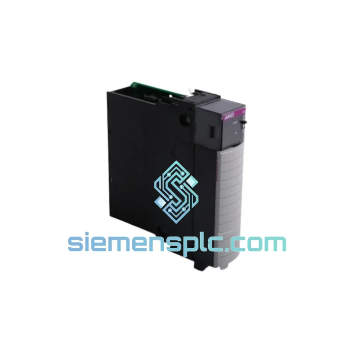
KUKA KRC400-195-245 KPC400-255-229 Robot Controller PC Unit
00-211-996 KRC4 PC Unit
Origin DE
PLC Controller Module
KUKA
RFQ Ready
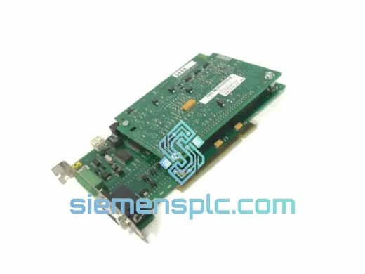
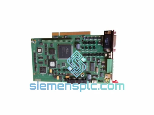
KUKA KRC4 00-168-334 00-181-563 KRC2 00-126-383 Robot Controller Board
Origin DE
Robot Controller Board