Omron
RFQ Ready
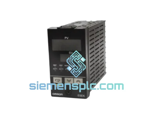
OMRON E5EK-PRR2-500 Temperature Controller – E5EK Series
Origin JP
Temperature Controller
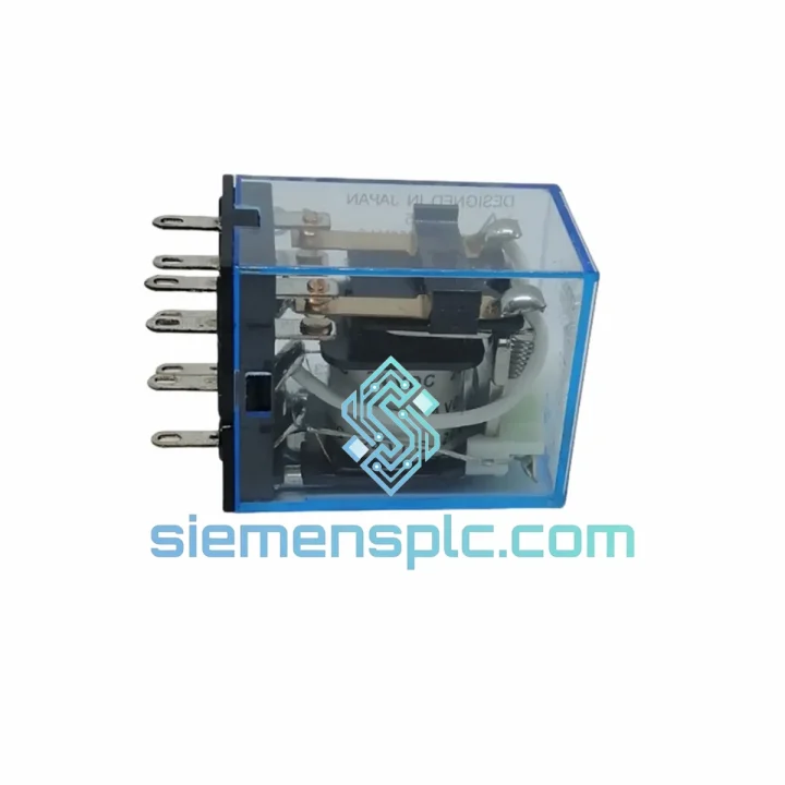
Request verified availability, condition, replacement risk review, packing options and courier lead time for MY2N-J.
Click Request Quote and the part number is inserted into the inquiry form automatically.
Core fields for model confirmation and RFQ routing. Detailed product narrative remains below.
The MY2N-J occupies a structurally critical position in discrete control architectures: it functions as the galvanic isolation boundary between low-voltage logic circuits and field-side power loads. In a typical PLC-driven panel, the digital output module operates at 24 VDC with a source current ceiling of 100–500 mA per channel. Directly switching inductive loads — motor contactors, solenoid valves, heating elements — from these outputs introduces two failure modes: back-EMF transients that exceed the output transistor’s collector-emitter breakdown voltage, and ground-loop noise that corrupts analog signal rails. The MY2N-J eliminates both vectors by interposing a magnetically coupled, mechanically isolated switching element between the logic domain and the load domain.
The relay’s 2PDT (2-Pole Double Throw) contact architecture provides two independent switching circuits from a single coil energization event. This is exploited in interlocking logic — for example, one pole breaks the forward-run contactor circuit while the second pole simultaneously closes the reverse-run inhibit path, enforcing mutual exclusion at the hardware level rather than relying solely on PLC software logic. This hardware-enforced interlocking is a requirement under IEC 60204-1 for Category 1 and Category 3 safety functions in machine control.
The N-J suffix encodes two field-critical features. The “N” designates a built-in LED coil status indicator, providing a direct visual confirmation of coil energization state without requiring a multimeter or test lamp — a measurable reduction in fault-isolation time during commissioning and maintenance. The “J” designates a manual override pushbutton that mechanically actuates the armature independent of coil voltage. This allows technicians to test downstream load circuits, verify wiring continuity, and perform functional checks on field devices before the control system is fully commissioned, without requiring a live PLC program or temporary jumper wires.
Real-time Stock & RFQ: [email protected] | WhatsApp: +86 18359268345
| Parameter | Specification |
|---|---|
| Model Number | MY2N-J |
| Brand | OMRON |
| Series | MY Series |
| Relay Type | General-Purpose Power Relay |
| Pole / Throw Configuration | 2PDT (DPDT) |
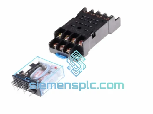
| Pin Base | 8-Pin Octal (plug-in) |
| Contact Material | Silver alloy (AgNi) |
| Contact Rating (Resistive) | 10 A @ 250 VAC / 10 A @ 30 VDC |
| Max. Switching Voltage | 250 VAC / 110 VDC |
| Max. Switching Current | 10 A |
| Max. Switching Power | 2,500 VA (AC) / 300 W (DC) |
| Coil Voltage Options | 6, 12, 24, 48, 100, 110, 120, 200, 220, 240 VAC/VDC |
| Coil Power Consumption | ≈ 1.6 W (DC) / 1.6 VA (AC) |
| Must Operate Voltage | ≤ 80% of rated coil voltage |
| Must Release Voltage | ≥ 10% of rated coil voltage (DC) / ≥ 20% (AC) |
| Operate Time | ≤ 20 ms |
| Release Time | ≤ 20 ms |
| Mechanical Life | 50,000,000 operations min. (no load) |
| Electrical Life | 500,000 operations min. (rated resistive load) |
| Insulation Resistance | ≥ 1,000 MΩ at 500 VDC |
| Dielectric Strength (Coil–Contact) | 2,000 VAC / 1 min |
| Dielectric Strength (Contact–Contact) | 1,000 VAC / 1 min |
| Vibration Resistance | 10–55 Hz, 1.5 mm double amplitude |
| Shock Resistance | 1,000 m/s² (operating) / 1,000 m/s² (destruction) |
| Ambient Temperature | -40°C to +70°C (operating, no icing) |
| Ambient Humidity | 5% to 85% RH |
| Degree of Protection | Flux-tight (MY2N-J) |
| Weight | Approx. 50 g |
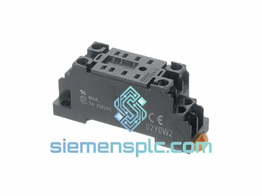
| Compatible Socket | PYF08A, PYF08A-E, PTF08A (with hold-down clip) |
| Certifications | UL, CSA, CE, RoHS, IEC 61810-1 |
| Country of Origin | Japan |
| Warranty | 12 months from date of shipment |
Magnetic Circuit and Armature Geometry: The MY2N-J employs a hinged-armature magnetic circuit. The coil generates a flux path through a laminated iron core and a pivoting armature. When coil current reaches the pull-in threshold (≤80% of rated voltage), the armature rotates against a calibrated return spring, simultaneously actuating both contact sets through a common insulating push-rod. This single-actuator, dual-contact design ensures that both poles switch within the same ≤20 ms window, eliminating the race condition that would exist if two independent relays were used for interlocking.
Contact Architecture and Arc Suppression: The AgNi (silver-nickel) contact material is selected for its resistance to arc erosion and contact welding under inductive load switching. At 10 A / 250 VAC, the arc energy at contact break is managed by the contact gap geometry and spring-driven separation velocity. For DC loads, the absence of a natural current zero crossing means arc extinction depends entirely on contact gap and separation speed — the MY2N-J’s contact spring force is rated to achieve reliable arc extinction at up to 110 VDC / 10 A within the 300 W switching power envelope.
EMC Design — Coil Transient Suppression: When the coil is de-energized, the collapsing magnetic field generates a back-EMF spike that can reach 10–50× the rated coil voltage in an unsuppressed circuit. The MY2N-J does not include an internal flyback diode (to preserve fast release time), so external suppression is required for DC coil versions: a flyback diode (e.g., 1N4007) across the coil terminals limits the spike to approximately 0.7 V above supply rail. For AC coil versions, a varistor or RC snubber is the standard approach. OMRON offers the SY-SS (AC) and SY-SD (DC) surge suppressor accessories that mount directly to the PYF socket, keeping the suppression element physically adjacent to the coil terminals and minimizing the loop area of the transient current path.
Flux-Tight Enclosure: The MY2N-J suffix designates a flux-tight (sealed against flux penetration during wave soldering, though this is a plug-in relay — the designation here refers to protection against contamination from cleaning agents and flux residue in the panel environment). The enclosure prevents ingress of conductive particulates that could bridge contact gaps or contaminate the coil bobbin, extending service life in environments with metallic dust or cutting fluid mist.
Manual Override Mechanism: The J-suffix pushbutton directly depresses the armature push-rod, bypassing the magnetic circuit entirely. The mechanical force required is calibrated to be achievable by hand without tools, while the button’s travel is limited to prevent over-travel that could damage the contact springs. This design allows single-technician commissioning: one person at the panel can actuate the relay while a second verifies field device response, without requiring a second person at the PLC programming terminal.
All MY2N-J units supplied through siemensplc.com are sourced from verified OMRON authorized distribution channels. Each unit carries original OMRON factory packaging with holographic authenticity labels, date codes, and lot traceability. Prior to dispatch, units undergo incoming inspection covering coil continuity (measured resistance vs. nominal coil resistance ±10%), contact resistance (≤100 mΩ per pole at 1 A test current), and physical inspection of the manual override button and LED indicator lens integrity.
Shipments originate from our warehouse in Xiamen, China — a major international logistics hub with direct access to Xiamen Gaoqi International Airport and Xiamen Port. Standard export packaging uses anti-static foam inserts within double-wall corrugated cartons, with desiccant packs for humidity-sensitive shipments. Typical transit times: 3–5 business days to Southeast Asia, 5–8 days to Europe and the Middle East, 7–12 days to the Americas, via DHL Express, FedEx International Priority, or UPS Worldwide Express depending on destination and urgency. All shipments include tracking numbers and commercial invoices with HS Code 8536.49 for customs clearance. A 12-month warranty covers manufacturing defects from the date of shipment. Warranty claims are processed with return merchandise authorization (RMA) within 3 business days of receipt.
Email: [email protected]
WhatsApp: +86 18359268345
Web: siemensplc.com
Location: Xiamen, China
© 2026 siemensplc.com. All rights reserved.
We check the full part number, brand, series and visible nameplate information before quotation.
Sales confirms stock path, condition option, quantity and realistic lead time for export dispatch.
DHL, FedEx, UPS or buyer courier arrangements can be reviewed with packing requirements.
Similar brand or category products for fast comparison and multi-item RFQ lists.