Siemens
In Stock OK
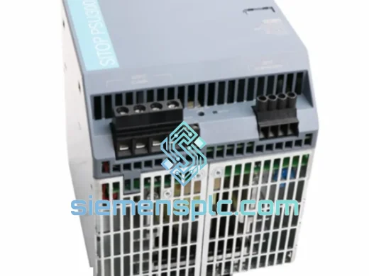
Siemens 6EP1333-1LB00 PLC Power Supply
Request verified availability, condition, replacement risk review, packing options and courier lead time for 6EP1333-1LB00.
BrandSiemens
Part Number6EP1333-1LB00
ConditionAvailability Check
Lead TimeRFQ Confirmation
DocumentsDatasheet / photos by RFQ
ShippingExport packing available
Auto-filled RFQ
6EP1333-1LB00
Click Request Quote and the part number is inserted into the inquiry form automatically.
- Reply by email: [email protected]
- WhatsApp / Tel: +86 18359268345
- Mon-Sat 9:00-18:00 GMT+8
Procurement Data
Key Product Information
Core fields for model confirmation and RFQ routing. Detailed product narrative remains below.
- Brand
- Siemens
- Primary Part Number
- 6EP1333-1LB00
- Product Type
- PLC Power Supply
- Series / Family
- SITOP
- Manufacturer
- Siemens AG, Germany
- Country of Origin
- DE
- Catalog Category
- Power Supplies
- Operating Temp.
- −20 °C to +60 °C
Model confirmed for inquiry
6EP1333-1LB00
Send quantity, destination and urgency. The RFQ form keeps this part number attached.
Request Quote
Product Overview
6EP1333-1LB00 Panel Dead? Cut Downtime Before It Cuts Your Margin
Three hours of unplanned downtime on a mid-scale production line can erase a week of margin. When the 24 V rail collapses and your S7-300 rack goes dark, the clock starts immediately — and it does not stop while you wait on a distributor’s lead-time quote. We carry the Siemens 6EP1333-1LB00 in bonded stock at our Xiamen facility. Orders confirmed before 14:00 CST ship the same afternoon. That is the only promise that matters when your line is stopped.
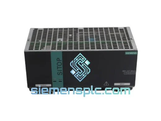
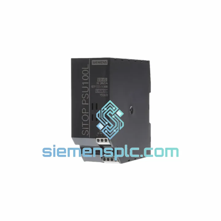
The 6EP1333-1LB00 belongs to the SITOP Smart family — Siemens’ workhorse single-phase power supply platform for industrial control panels. It converts wide-range AC input (120/230 V, auto-select) to a regulated 24 V DC output at 5 A continuous, 120 W total. The unit mounts on a standard 35 mm DIN rail, requires no firmware configuration, and integrates directly into any S7-300, S7-400, or ET 200 distributed I/O installation. It is not a generic PSU — it is a precision instrument built to Siemens’ IEC 61131-2 supply specifications.
URGENT REQUIREMENT? Contact: [email protected] | WhatsApp: +86 18359268345
Quick Technical Datasheet
| Parameter | Value | Status |
|---|---|---|
| Order Number | 6EP1333-1LB00 | ✅ Ready to Ship |
| Product Family | SITOP Smart | 100% Original |
| Manufacturer | Siemens AG, Germany | — |
| AC Input Range | 85–264 V AC (wide-range, auto) | No jumper required |
| Input Frequency | 47–63 Hz | — |
| DC Output Voltage | 24 V DC (adjustable 22.8–26.4 V) | Front potentiometer |
| Rated Output Current | 5 A | 10 A peak / 5 s |
| Rated Output Power | 120 W | — |
| Efficiency | ≥ 87% | — |
| Ripple & Noise | < 50 mV pk-pk | — |
| DIN Rail | 35 mm (EN 60715) | Tool-free snap mount |
| Enclosure Rating | IP20 | Panel installation |
| Operating Temperature | −20 °C to +60 °C | Derate >45 °C |
| Storage Temperature | −40 °C to +85 °C | — |
| Relative Humidity | 95% RH, non-condensing | — |
| Dimensions (W×H×D) | 55 × 125 × 125 mm | — |
| Weight | ~1,180 g | — |
| Parallel Operation | Up to 2 units | Voltage-match required |
| Short-Circuit Response | Electronic fold-back, auto-restart | — |
| DC OK Indicator | Green LED | — |
| Certifications | CE / UL / cUL / GL | — |
| Country of Origin | Germany | — |
| Dispatch Lead Time | ✅ Same-day dispatch on orders before 14:00 CST | |
Troubleshooting & Replacement Tips
Fault Pattern A — Output Rail Collapses, LED Extinguished
The DC OK LED going dark with AC input confirmed present is a primary-side failure signature. The internal NTC inrush limiter degrades over years of thermal cycling; once it opens, the unit cannot start. Verify AC at terminals L and N first — a dead LED with no AC input is a wiring or upstream breaker issue, not a PSU fault. If AC is confirmed and the LED stays off, the unit is condemned. Do not attempt internal repair; primary-side voltages exceed 400 V DC on the bulk capacitor even after AC removal. Discharge time is a minimum of 60 seconds — treat the unit as live until you have confirmed otherwise with a meter.
Fault Pattern B — Intermittent CPU Resets Under Load Switching
This is the failure mode that wastes the most diagnostic time. The output voltage appears correct at idle — 24.0 V, green LED on — but the PLC CPU resets every time a large contactor or servo drive engages. The root cause is secondary-side electrolytic capacitor aging: ESR rises, the output impedance increases, and the voltage dips below the CPU’s brownout threshold during load transients. Measure output voltage with an oscilloscope or a fast-response multimeter set to min/max capture while deliberately switching the largest load on the 24 V bus. A dip below 21.6 V during switching confirms the PSU is the culprit. Replace it — do not attempt to compensate with a larger output capacitor on the bus bar; that masks the symptom and delays the inevitable hard failure.
Fault Pattern C — Thermal Cutout, Cyclic Restart Every 30–90 Seconds
The 6EP1333-1LB00 has internal over-temperature protection that shuts the output and restarts automatically once the internal temperature drops. If you observe a cyclic restart pattern, measure the total 24 V bus current with a clamp meter before assuming the PSU is faulty. A bus current above 5 A means the load has grown beyond the PSU’s rating — a common situation after incremental additions of field devices over years of plant expansion. If the load is within spec, check cabinet ventilation: the unit requires 50 mm of free space above and below for convection airflow. A blocked ventilation slot in a sealed cabinet on a hot summer day is enough to trigger thermal cutout at rated load.
Step-by-Step Replacement Procedure
- Isolate and verify. Open the upstream MCB feeding the panel. Apply LOTO per your site procedure. Confirm AC input is dead at the PSU terminals L and N with a calibrated voltage tester — not a neon screwdriver. Wait 60 seconds for internal capacitors to discharge before proceeding.
- Document before you disconnect. Photograph the terminal block wiring from both the AC input side (top) and DC output side (bottom). If your panel uses wire ferrules and numbered sleeves, this step takes 10 seconds. If it does not, label every wire with tape flags before removal — a transposed 0 V and +24 V connection on restart will destroy field devices.
- Remove DC output wiring first. Loosen the +24 V and 0 V output terminals using a 0.6 × 3.5 mm flat-blade screwdriver. Pull the wires clear and tape the ends to prevent accidental contact.
- Remove AC input wiring. Loosen L, N, and PE terminals. The PE (ground) terminal is typically green/yellow and connects to the panel earth bar — do not omit it on the replacement unit.
- Release the DIN rail clip. Insert a flat-blade screwdriver into the bottom DIN rail clip slot and lever it downward. The unit will tilt forward — lift it off the rail from the top hook. Note the clip orientation for reinstallation.
- Mount the replacement unit. Hook the top of the new 6EP1333-1LB00 onto the upper edge of the DIN rail. Press the bottom firmly until the spring clip snaps audibly. Apply a firm lateral tug to confirm the unit is locked — a unit that slides on the rail is not properly seated.
- Reconnect in reverse order. PE first, then L and N, then +24 V and 0 V. Torque all screw terminals to 0.8 N·m. Under-torqued terminals are the leading cause of resistive heating faults in the first 6 months after replacement.
- Pre-energization check. Confirm the output voltage potentiometer is at the factory default (24.0 V, mid-position). If your system requires a trimmed voltage — for example, 24.5 V to compensate for a long cable run to a remote I/O rack — set it now with the unit powered but unloaded, before connecting the bus bar.
- Energize and verify. Close the MCB. The green DC OK LED should illuminate within 2 seconds. Measure output voltage under full load. Log the replacement: date, replaced unit serial number, new unit serial number, measured output voltage at full load. This record is your evidence if a warranty claim arises.
Parallel Redundancy Configuration Note
The 6EP1333-1LB00 supports parallel operation of two units for N+1 redundancy. Before connecting outputs in parallel, trim both units to identical output voltages — within ±0.05 V — using the front potentiometer and a calibrated multimeter. A mismatch of more than 0.1 V will cause the higher-voltage unit to carry the entire load while the lower-voltage unit contributes nothing, negating the redundancy benefit and accelerating wear on the loaded unit. There are no DIP switches, no firmware, and no TIA Portal configuration required for this PSU — it is a pure analog device.
Reliability in Harsh Conditions
The SITOP Smart platform was validated against the conditions that actually exist on factory floors — not the idealized environments described in generic PSU datasheets. The 6EP1333-1LB00 meets IEC 60068-2-6 vibration testing: sinusoidal vibration at 10–58 Hz, 0.075 mm amplitude, and 58–500 Hz at 1 g. This covers the continuous vibration spectrum of press lines, compressor skids, and mobile equipment panels where cheaper PSUs develop cracked solder joints within 18 months.
The wide-range AC input (85–264 V AC) is not a marketing feature — it is a practical necessity in industrial facilities where the supply voltage fluctuates with large motor starts and transformer tap changes. The unit maintains output regulation within ±1% across the full input range without requiring manual voltage selection. In regions where the nominal supply is 110 V or 220 V, the same unit works without modification.
Thermal design uses a natural convection cooling strategy with no moving parts — no fan to fail, no filter to clog. The operating temperature ceiling of +60 °C covers non-air-conditioned machine rooms in tropical climates. Above +45 °C ambient, derate the output current by 2.5% per degree Celsius: at +55 °C, the safe continuous output is approximately 3.75 A. Ignoring this derating curve is the single most common cause of premature PSU failure in hot climates — the unit does not fail immediately, it degrades over months until a hot summer day pushes it over the edge.
Humidity performance is rated to 95% RH non-condensing, covering coastal installations and high-humidity manufacturing environments such as food processing and textile plants. In environments where condensation is a risk — outdoor enclosures, unheated buildings in cold climates — install a cabinet heater or anti-condensation heater to maintain the internal temperature above the dew point. The PSU itself does not have conformal coating as standard; in aggressive environments, a field-applied conformal coating spray (IEC 61086 compliant) on the PCB extends service life significantly.
Global Express Logistics
Our Xiamen warehouse operates on a same-day dispatch model for orders confirmed before 14:00 CST. The pick-pack-inspect cycle for a single 6EP1333-1LB00 takes under 20 minutes. Export documentation — commercial invoice, packing list, HS code pre-classification under 8504.40, and certificate of origin — is generated in parallel with physical packing, not sequentially. This parallel workflow eliminates the documentation bottleneck that adds 24 hours to shipments from suppliers who treat paperwork as an afterthought.
Standard shipping options are DHL Express Worldwide and FedEx International Priority. Typical door-to-door transit times from Xiamen: Western Europe 2–3 business days, Eastern Europe 3–4 days, North America 3–5 days, Southeast Asia 1–2 days, Middle East 2–3 days, Australia 3–4 days, South America 4–6 days. All shipments are fully insured and tracked end-to-end. Waybill numbers are provided within 2 hours of dispatch — not the next morning.
For customers in markets with complex import procedures — Brazil, India, Russia, Turkey — we prepare the commercial invoice with the precise technical description and declared value required by local customs authorities. We have cleared shipments through over 60 customs jurisdictions and maintain a library of country-specific documentation templates. If your import requires an end-user certificate, a specific HS code declaration, or a phytosanitary certificate for wooden packaging, contact us before ordering. We will advise on the exact documentation package required and prepare it without additional charge.
Planned maintenance orders of 5 units or more qualify for sea freight consolidation through our Xiamen port partners. FCL and LCL options are available to European, North American, and Australian ports. Transit times are 18–28 days depending on destination port. For shutdown maintenance where the delivery window is measured in weeks rather than hours, sea freight reduces logistics cost by 60–70% compared to express air. Contact us for a combined air/sea split-shipment quote if you need some units urgently and the remainder on a slower schedule.
Contact Information
Email: [email protected]
WhatsApp: +86 18359268345
Web: siemensplc.com
© 2026 siemensplc.com. All rights reserved.
Ready to quote
[email protected]
Send This Part Number to Sales
RFQ workflow
Quality workflow ->
Confirmation Process
01Model confirmation
We check the full part number, brand, series and visible nameplate information before quotation.
02Availability reply
Sales confirms stock path, condition option, quantity and realistic lead time for export dispatch.
03Packing & courier
DHL, FedEx, UPS or buyer courier arrangements can be reviewed with packing requirements.
Continue sourcing
Browse full catalog ->
Related Automation Parts
Similar brand or category products for fast comparison and multi-item RFQ lists.
Siemens
RFQ Ready
SIEMENS 6EP1332-1LB00 Industrial Power Supply
SITOP
Origin DE
Industrial Power Supply
Siemens
RFQ Ready
Siemens 6EP1437-2BA20 Industrial Power Supply – SITOP PSU300S
SITOP
Origin DE
Industrial Power Supply