Vibro-Meter
RFQ Ready
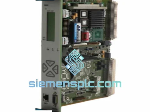
VIBRO-METER VM600-CPU-M-200-595-074-122 CPU Module
VM600 Rack Processor
Origin Switzerland
Vibration Monitoring CPU Module
Request verified availability, condition, replacement risk review, packing options and courier lead time for VIBRO-METER.
Click Request Quote and the part number is inserted into the inquiry form automatically.
Core fields for model confirmation and RFQ routing. Detailed product narrative remains below.
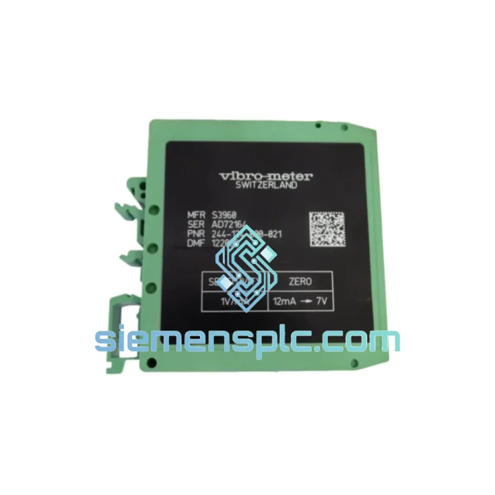
The VIBRO-METER 244-124-000-021 is a compression-mode piezoelectric seismic accelerometer manufactured by Meggitt SA (VIBRO-METER division, Fribourg, Switzerland) for deployment within the VM600 Machinery Protection System. Its function within a protection loop is unambiguous: it occupies the field-sensing tier, converting mechanical inertial loading at the bearing housing or machine casing into a proportional electrical charge signal (pC) that feeds directly into a VM600-compatible charge amplifier or transmitter card. The integrity of every downstream measurement — amplitude trending, spectral analysis, alarm threshold enforcement, and emergency trip actuation — is a direct function of this transducer’s output fidelity.
Unlike IEPE (Integrated Electronics Piezo-Electric) sensors, the 244-124-000-021 operates in passive charge-output mode. There is no internal amplifier stage. This architectural choice is deliberate: it removes the primary thermal failure mechanism from the sensing head, extending reliable service life in environments where bearing housing temperatures routinely exceed 80 °C and where IEPE bias current circuits would exhibit gain drift or saturation. The charge signal is transmitted via low-noise coaxial cable to the conditioning electronics, where integration, filtering, and scaling are performed under controlled thermal conditions inside the VM600 rack enclosure.
The transducer is rated for continuous operation across a broad temperature envelope and is housed in a hermetically welded 316L stainless-steel body. Its mounting interface accommodates threaded stud or flange configurations, consistent with API 670 installation requirements for turbomachinery bearing housings. The sensor is applicable to gas turbines, steam turbines, centrifugal and axial compressors, large pumps, and gearboxes — any rotating asset where vibration-based condition monitoring is mandated by plant safety or insurance requirements.
Real-time Stock & RFQ: [email protected] | WhatsApp: +86 18359268345
| Parameter | Specification |
|---|---|
| Part Number | 244-124-000-021 |
| Manufacturer | Meggitt SA — VIBRO-METER Division, Fribourg, Switzerland |
| Compatible System | VM600 Machinery Protection System (MPS) |
| Transducer Technology | Compression-mode piezoelectric crystal stack (charge output) |
| Output Mode | Charge (pC/g) — passive, no internal electronics |
| Measurement Axis | Uniaxial (single-axis seismic) |
| Usable Frequency Band | 2 Hz – 10 kHz (±3 dB, within flat response region) |
| Mechanical Resonance Frequency | > 25 kHz (above measurement bandwidth) |
| Operating Temperature Range | −40 °C to +120 °C (sensor body); cable rating per installation spec |
| Shock Resistance | ≥ 2,000 g peak (11 ms half-sine pulse) |
| Crystal Insulation Resistance | > 10¹² Ω across full operating temperature range |
| Housing Material | 316L stainless steel, hermetically welded |
| Ingress Protection | IP67 (sealed housing, connector mated) |
| Electrical Interface | MIL-C-5015 series circular connector (coaxial signal + shield) |
| Mounting Configuration | Threaded stud or flange mount per API 670 installation drawing |
| Approximate Mass | 600 g |
| Applicable Standards | API 670 (5th Ed.), ISO 10816-3, ISO 20816-3 |
| Origin | Switzerland |
| Warranty | 12 months from shipment date against manufacturing defects |
Charge-Mode Transduction and Thermal Decoupling: The 244-124-000-021 uses a stacked piezoelectric crystal assembly operating in compression mode. Mechanical vibration at the mounting surface applies cyclic stress to the crystal stack, inducing charge separation across the crystal faces at a rate proportional to applied acceleration. Because the charge signal is generated passively — with no bias voltage, no FET input stage, and no internal op-amp — the sensor head contains zero active components subject to thermal degradation. This decouples the sensing element’s performance from ambient temperature variation in a way that IEPE architectures cannot achieve. At 120 °C continuous, an IEPE sensor’s internal amplifier may exhibit gain shifts of 1–3 dB; the 244-124-000-021 maintains crystal sensitivity within its rated tolerance band across the full thermal envelope.
EMC Shielding and Ground Loop Suppression: The coaxial cable interface, combined with the all-metal housing, forms a continuous electrostatic shield from the crystal assembly to the charge amplifier input terminal. This construction provides effective attenuation of capacitively coupled interference from variable-frequency drives (VFDs), high-voltage bus bars, and adjacent motor windings — all of which generate broadband EMI in the 1–100 kHz range that overlaps with bearing defect frequencies. The shield is terminated at a single point (the charge amplifier chassis ground) to prevent differential ground potential between the sensor mounting surface and the rack from forming a ground loop. A ground loop of even 50 mV at 50 Hz would inject a −40 dB artifact into the vibration baseline, sufficient to mask early-stage bearing defect signatures at low running speeds.
Resonance Placement and Flat-Band Integrity: The internal mass-spring geometry of the 244-124-000-021 is tuned to place the first mechanical resonance above 25 kHz. This ensures that the measurement bandwidth (2 Hz – 10 kHz) lies entirely within the flat response region, where sensitivity is linear and phase response is monotonic. Operating below resonance is mandatory for accurate amplitude measurement: within one octave of resonance, sensitivity rises by 6 dB/octave, producing amplitude errors that would cause false alarm conditions in the VM600 protection logic. The 25 kHz resonance margin provides more than one decade of separation from the upper measurement limit, maintaining amplitude accuracy within ±3 dB across the full rated band.
Hermetic Sealing and Crystal Insulation Stability: The hermetically welded housing prevents moisture ingress into the crystal assembly over the sensor’s service life. Moisture contamination of a piezoelectric element degrades the crystal’s surface insulation resistance, which manifests as low-frequency signal droop (high-pass corner frequency shift) and DC baseline drift. In practice, a degraded insulation resistance of 10⁸ Ω (versus the rated 10¹² Ω) shifts the low-frequency −3 dB point from 2 Hz to approximately 200 Hz, eliminating the sensor’s ability to capture slow-roll vibration data below 12,000 RPM — a critical measurement for turbomachinery startup and coast-down analysis. The hermetic construction maintains insulation resistance above 10¹² Ω indefinitely under normal service conditions.
All VIBRO-METER 244-124-000-021 units supplied by siemensplc.com are sourced through verified procurement channels with full OEM traceability. Each unit is inspected prior to dispatch: label and serial number verification against manufacturer records, housing seal integrity check, connector pin inspection for corrosion or mechanical damage, and electrical continuity verification of the coaxial signal path. Units are shipped in original manufacturer packaging with all accompanying documentation intact. No repackaging, relabeling, or modification is performed.
Logistics operations are based in Xiamen, Fujian Province, China — a primary export hub with direct carrier access to DHL Express, FedEx International Priority, TNT, and UPS Worldwide Expedited. Standard dispatch for in-stock units is within 1–3 business days. Expedited same-day dispatch is available for plant maintenance emergencies. Transit times to Western Europe and North America are typically 3–5 business days via express services. For volume orders, LCL and FCL sea freight options are available with full export documentation including commercial invoice, packing list, certificate of conformity, and customs declaration (HS code pre-classified).
A 12-month warranty against manufacturing defects applies from the date of shipment. Warranty claims are processed via photographic inspection of the returned unit. Confirmed defective units are replaced or credited without extended RMA delays. Expedited replacement shipment is available for plant-critical applications.
📧 Email: [email protected]
📱 WhatsApp: +86 18359268345
🌐 Web: siemensplc.com
📍 Location: Xiamen, China
© 2026 siemensplc.com. All rights reserved.
We check the full part number, brand, series and visible nameplate information before quotation.
Sales confirms stock path, condition option, quantity and realistic lead time for export dispatch.
DHL, FedEx, UPS or buyer courier arrangements can be reviewed with packing requirements.
Similar brand or category products for fast comparison and multi-item RFQ lists.