Yokogawa
RFQ Ready
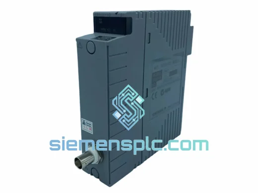
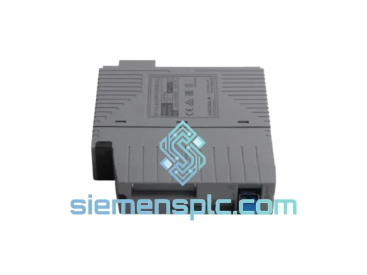
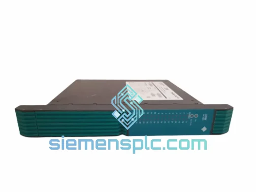
Yokogawa PSCDM024DCBAN Safety Discrete Module
ProSafe-RS
Origin JP
Safety Instrumented System Module
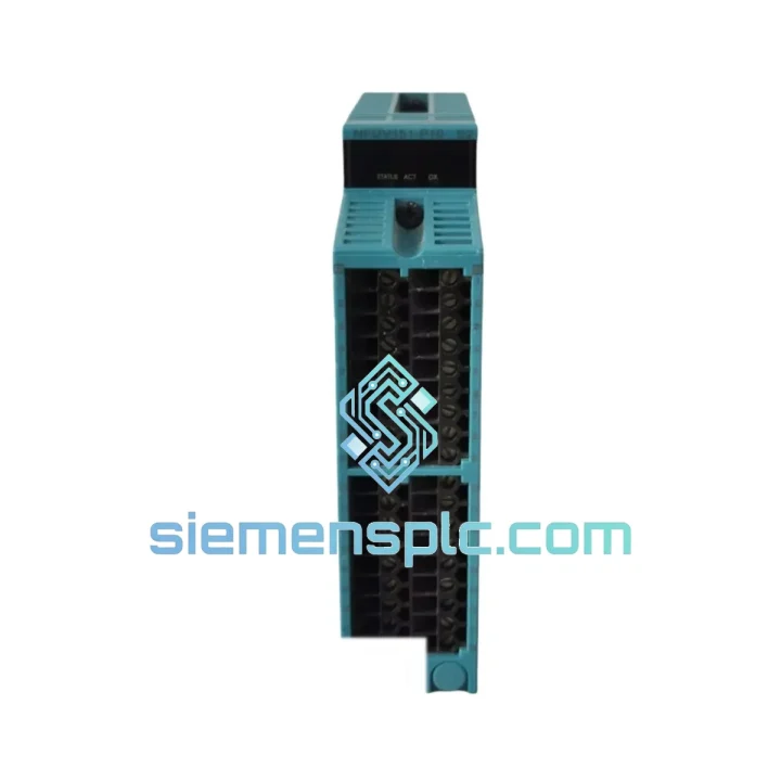
Request verified availability, condition, replacement risk review, packing options and courier lead time for NFDV151-P10.
Click Request Quote and the part number is inserted into the inquiry form automatically.
Core fields for model confirmation and RFQ routing. Detailed product narrative remains below.
In a Safety Instrumented System, the digital input subsystem occupies the most critical position in the signal chain: it is the first hardware boundary between raw field process states and the logic solver’s decision engine. Any undetected open-circuit fault, contact weld, or signal ambiguity at this boundary directly degrades the Probability of Failure on Demand (PFD) of the entire Safety Instrumented Function (SIF). The YOKOGAWA NFDV151-P10 S2 is a 16-channel digital input module engineered specifically for the ProSafe-RS Safety Instrumented System platform. Certified to IEC 61508 Edition 2 at SIL 2, it delivers deterministic signal acquisition, hardware-level diagnostic coverage exceeding 90%, and optical isolation rated at 500 V AC between field terminals and the backplane bus — all within a single chassis slot.
The module mounts directly into the ProSafe-RS I/O chassis and communicates with the Safety Controller (SCS) via the ProSafe-RS proprietary high-speed node bus. This bus operates on a fixed-cycle protocol with bounded latency, meaning the SCS receives fresh input data from all 16 channels within a verifiable and repeatable time window on every scan cycle. This determinism is not incidental — it is a design requirement for SIF response time calculations under IEC 61511 Clause 11, where the input module’s contribution to total loop response time must be quantified and documented during the safety lifecycle.
Each input channel accepts either dry-contact or wet-contact field signals, selectable per channel group via the ProSafe-RS Engineering Tool. The field-side signal conditioning circuit includes a configurable input filter with an adjustable time constant, allowing the system integrator to tune the balance between response speed and noise rejection based on cable run length, field device type, and the electromagnetic environment of the installation. Mechanical field devices — pressure switches, limit switches, solenoid valve position feedback contacts — generate contact bounce that, without adequate filtering, can produce spurious input transitions at the backplane interface. The NFDV151-P10 S2’s filter stage eliminates this without introducing latency that would violate the SIF response time budget.
Real-time Stock & RFQ: [email protected] | WhatsApp: +86 18359268345
| Parameter | Specification |
|---|---|
| Part Number | NFDV151-P10 S2 |
| Manufacturer | YOKOGAWA Electric Corporation |
| Platform | ProSafe-RS Safety Instrumented System |
| Module Function | Digital Input (DI), 16-channel |
| Input Signal Type | Dry contact / Wet contact (configurable per channel group) |
| Input Filter Time Constant | Configurable via ProSafe-RS Engineering Tool |
| Optical Isolation Voltage | 500 V AC (field side to backplane) |
| Safety Integrity Level | SIL 2 per IEC 61508 Ed.2 / IEC 61511 |
| Diagnostic Coverage (DC) | >90% per IEC 61508 hardware fault tolerance requirements |
| Hardware Architecture | 1oo2D (one-out-of-two with diagnostics) per channel pair |
| Node Bus Interface | ProSafe-RS internal node bus (proprietary fixed-cycle serial) |
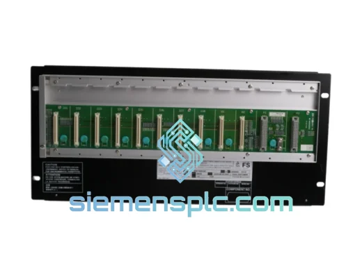
| Mounting | ProSafe-RS I/O chassis (DIN rail compatible base unit) |
| Operating Temperature | 0 °C to +60 °C |
| Storage Temperature | -20 °C to +70 °C |
| Relative Humidity | 5% to 95% RH, non-condensing |
| EMC Compliance | IEC 61000-4 series (ESD, EFT, surge, conducted RF, radiated RF); CE marked |
| Certification Standards | IEC 61508 Ed.2, IEC 61511, TÜV Rheinland certified |
| Module Weight | Approx. 200 g |
| Country of Origin | Japan |
| Warranty | 12 months from confirmed shipment date |
At the silicon level, the NFDV151-P10 S2 implements a dual-path acquisition architecture within its onboard ASIC. Each of the 16 physical field contacts is sampled by two independent acquisition circuits operating in parallel. On every diagnostic cycle, the ASIC compares the binary state reported by each path. A mismatch — indicating a stuck-at fault in one acquisition circuit, an intermittent contact, or a wiring fault that affects only one path — is immediately flagged as a diagnostic alarm and transmitted to the SCS via the node bus status word. This hardware-level 1oo2D structure achieves diagnostic coverage above 90% without depending on software-based self-test routines, which are inherently limited by the SCS scan cycle rate.
The optical isolation stage uses phototransistor-based couplers with precisely defined switching thresholds. These thresholds are selected to reject common-mode transients generated by field cabling routed in shared cable trays with high-voltage motor drive output conductors or solenoid valve wiring — environments where induced transients can reach several hundred volts in microsecond timescales. The 500 V AC isolation rating provides a margin well above the transient amplitudes encountered in typical process plant cable infrastructure.
PCB-level EMC hardening is implemented through three complementary mechanisms: transient voltage suppression (TVS) diodes on all field-side terminals to clamp fast transients before they reach the isolation stage; ground plane partitioning that physically separates the field-side copper pour from the logic-side copper pour, preventing capacitive coupling of high-frequency noise across the isolation barrier; and ferrite bead filtering on the backplane power supply rails to attenuate conducted emissions from the chassis power distribution network. This layered approach eliminates the need for external EMC filtering hardware in the marshalling cabinet, reducing installation cost and cabinet footprint.
The module’s onboard microcontroller executes the diagnostic test cycle asynchronously from the SCS scan cycle. This independence ensures that diagnostic coverage is maintained even during periods of elevated SCS processor loading — for example, during large-scale cause-and-effect matrix evaluations triggered by simultaneous multi-point process upsets. Diagnostic results are time-stamped at the module level and transmitted to the SCS with each node bus frame, enabling the SCS event log to record the precise moment of fault detection relative to the process timeline, which is essential for post-incident root-cause analysis under IEC 61511 management of functional safety requirements.
Every NFDV151-P10 S2 unit dispatched by siemensplc.com is sourced through verified supply channels and passes a structured pre-shipment inspection before packaging. Authenticity verification follows YOKOGAWA’s official part marking standards: holographic security labels, PCB date codes, revision markings, and connector pin condition are all checked against reference documentation. Where bench test equipment is available, modules are powered and checked for basic operational status prior to final packaging.
All shipments originate from our warehouse in Xiamen, China — a primary international logistics hub with direct air freight access to Europe, the Middle East, Southeast Asia, South Asia, and the Americas. Standard international orders are dispatched within 3–5 business days of order confirmation. Urgent in-stock requirements can be accommodated with same-day or next-business-day dispatch. Every shipment includes full tracking, commercial invoice, and packing list. Export documentation — including certificates of origin and any market-specific compliance paperwork — is available upon request to support customs clearance in regulated import markets.
A 12-month warranty covers all supplied units against manufacturing defects and functional failures under normal operating conditions as defined by YOKOGAWA’s published environmental specifications. Warranty claims are acknowledged within 2 business days of receipt of the returned unit, with replacement or repair options available based on stock availability and fault assessment.
Email: [email protected]
WhatsApp: +86 18359268345
Web: siemensplc.com
Location: Xiamen, China
© 2026 siemensplc.com. All rights reserved.
We check the full part number, brand, series and visible nameplate information before quotation.
Sales confirms stock path, condition option, quantity and realistic lead time for export dispatch.
DHL, FedEx, UPS or buyer courier arrangements can be reviewed with packing requirements.
Similar brand or category products for fast comparison and multi-item RFQ lists.