Bently Nevada
RFQ Ready
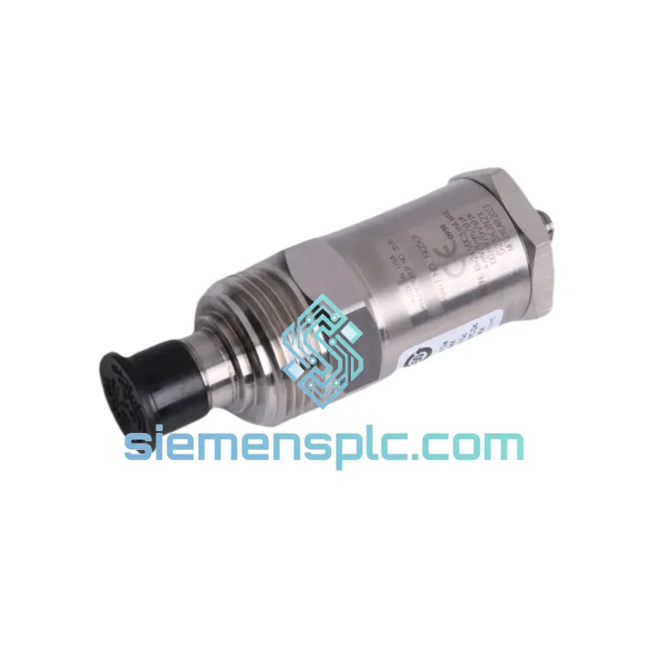
Bently Nevada RS901104-03-050-10-01 Proximitor Sensor – 3300 XL Series
3300 XL
Origin US
Proximitor Sensor
Request verified availability, condition, replacement risk review, packing options and courier lead time for 190501-09-99-00.
Click Request Quote and the part number is inserted into the inquiry form automatically.
Core fields for model confirmation and RFQ routing. Detailed product narrative remains below.
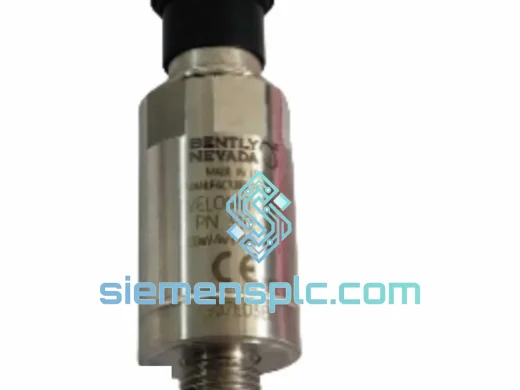
The Bently Nevada 190501-09-99-00 is a top-exit, 9 mm-body piezoelectric velocity transducer belonging to the Velomitor CT (Ceramic Technology) product family. Its primary function within a machinery protection control loop is to convert absolute casing vibration into a proportional analog voltage signal, which is then conditioned by a compatible monitor module — typically the Bently Nevada 3500/42M or 1900/65A — and compared against alarm and danger setpoints in real time. Unlike proximity probes that measure shaft relative motion, this sensor measures absolute structural velocity at the bearing housing or machine casing, making it the preferred instrument for API 670-compliant seismic monitoring on steam turbines, centrifugal compressors, and large rotating machinery where shaft access is impractical.
The ceramic sensing element at the core of the 190501-09-99-00 is a lead zirconate titanate (PZT) crystal stack mechanically coupled to a seismic mass. When the housing accelerates, the inertial mass compresses the crystal, generating a charge proportional to velocity after integration through the internal signal conditioning circuit. The CT designation specifically refers to the ceramic formulation used, which exhibits a Curie temperature well above 300 °C — providing a substantial thermal margin relative to the 121 °C rated operating limit and ensuring piezoelectric coefficient stability over the full service life without depolarization drift.
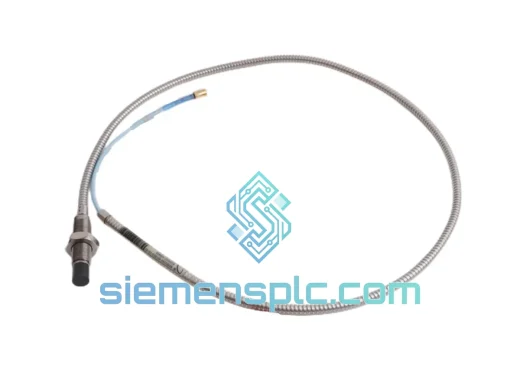
The top-exit cable configuration of this variant is selected when radial clearance around the sensor body is constrained — common on turbine pedestals and compressor bearing caps where adjacent piping or structural members limit side-exit routing. The 9 mm probe body diameter allows installation in compact mounting bosses without requiring custom machined adapters in most OEM machine designs.
Real-time Stock & RFQ: [email protected] | WhatsApp: +86 18359268345
| Parameter | Specification |
|---|---|
| Part Number / SKU | 190501-09-99-00 |
| Product Family | Velomitor CT (Ceramic Technology) |
| Manufacturer | Bently Nevada (Baker Hughes) |
| Sensor Technology | Piezoelectric (PZT ceramic element), seismic mass design |
| Measurement Quantity | Absolute casing / structural velocity |
| Sensitivity | 100 mV/in/s ± 10% (3.94 mV/mm/s) |
| Frequency Response | 2 Hz – 1,000 Hz (±3 dB) |
| Amplitude Range | 0 – 50 in/s pk (0 – 1,270 mm/s pk) |
| Resonant Frequency | ≥ 22,000 Hz |
| Transverse Sensitivity | ≤ 5% of axial sensitivity |
| Output Impedance | < 100 Ω |
| Operating Temperature | −40 °C to +121 °C (−40 °F to +250 °F) |
| Storage Temperature | −55 °C to +150 °C |
| Housing Material | 316L Stainless Steel |
| Sealing / IP Rating | IP67 (IEC 60529) |
| Cable Exit Orientation | Top-exit (axial) |
| Probe Body Diameter | 9 mm |
| Mounting Thread | 1/4-28 UNF or M8 × 1.25 (adapter dependent) |
| Connector Type | 2-pin MIL-C-5015 style |
| Approximate Weight | 380 g |
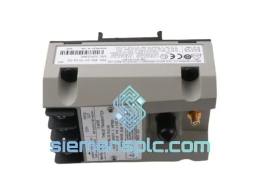
| Compatible Monitors | Bently Nevada 3500/42M, 3500/45, 3500/46M, 1900/65A |
| Applicable Standards | API 670 (5th Ed.), ISO 10816-3, IEC 60068-2 |
| Warranty | 12 months from date of shipment |
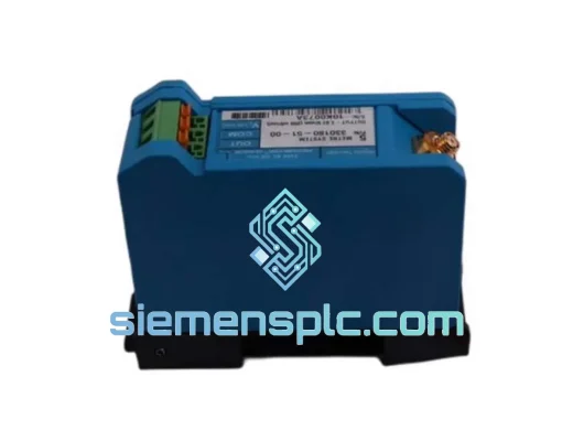
The internal signal chain of the 190501-09-99-00 begins at the PZT ceramic stack, which is pre-loaded under controlled compressive stress during assembly to linearize its charge-displacement relationship and suppress hysteresis. The seismic mass is precision-machined to a target inertial value that, combined with the crystal stiffness, sets the mechanical resonant frequency above 22 kHz — placing it well outside the 2–1,000 Hz measurement band and preventing resonance amplification from corrupting velocity readings during normal operation.
The internal charge amplifier converts the high-impedance crystal output to a low-impedance voltage signal (<100 Ω source impedance), which is critical for driving long cable runs — often 30–100 m in plant installations — without signal attenuation or susceptibility to capacitive loading. The amplifier circuit incorporates a high-pass filter pole at approximately 2 Hz to block DC drift and very low-frequency thermal expansion artifacts, and a low-pass pole near 1,000 Hz to define the upper measurement boundary and attenuate high-frequency structural noise that would otherwise alias into the velocity measurement.
EMC performance is achieved through a combination of the 316L stainless steel housing acting as a Faraday shield, internal circuit-level filtering on the power supply rails, and the differential signal architecture used when paired with Bently Nevada monitor inputs. The IP67 sealing is accomplished via a dual O-ring arrangement at the cable exit gland and a hermetic glass-to-metal seal at the connector interface, preventing moisture ingress that would degrade insulation resistance and introduce noise floors incompatible with early-fault detection thresholds.
The top-exit cable geometry routes the signal conductor away from the mounting surface, reducing the risk of cable damage from thermal cycling-induced movement at the machine casing — a failure mode observed with side-exit variants in high-temperature turbine applications where differential thermal expansion between the sensor body and the machine casting causes repeated cable flexing at the exit point.
Every Bently Nevada 190501-09-99-00 unit supplied by siemensplc.com is sourced through verified industrial automation supply channels and subjected to incoming inspection covering visual integrity, connector pin continuity, housing marking authenticity, and documentation traceability. Units are stored in a climate-controlled warehouse in Xiamen, China, in anti-static foam-lined packaging to prevent electrostatic discharge damage to the internal amplifier circuit during storage.
Outbound logistics from Xiamen are handled via DHL Express, FedEx International Priority, and UPS Worldwide Expedited, with typical transit times of 3–5 business days to major industrial hubs in Europe, North America, Southeast Asia, and the Middle East. All shipments include a commercial invoice, packing list, and certificate of origin. For project orders requiring consolidated documentation packages — including material test reports, calibration records, and third-party inspection certificates — these are prepared and transmitted prior to dispatch.
A 12-month warranty covers manufacturing defects and functional failures under rated operating conditions. Warranty claims are processed with a target response time of 48 hours from receipt of the defective unit, with replacement dispatch within 5 business days upon fault confirmation.
Email: [email protected]
WhatsApp: +86 18359268345
Web: siemensplc.com
Location: Xiamen, China
© 2026 siemensplc.com. All rights reserved.
We check the full part number, brand, series and visible nameplate information before quotation.
Sales confirms stock path, condition option, quantity and realistic lead time for export dispatch.
DHL, FedEx, UPS or buyer courier arrangements can be reviewed with packing requirements.
Similar brand or category products for fast comparison and multi-item RFQ lists.