GE Fanuc
RFQ Ready
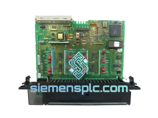
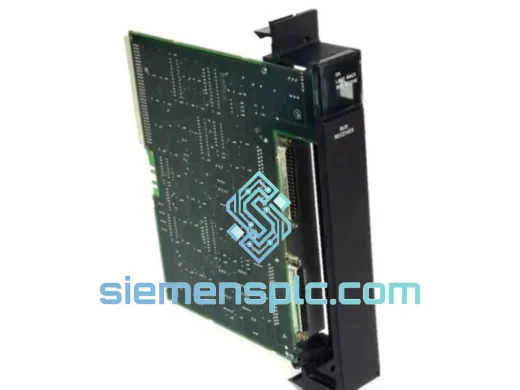
GE Fanuc IC697BEM711 Bus Receiver Module – Series 90-70
Fanuc
Origin US
Bus Receiver Module
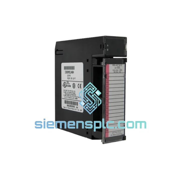
Request verified availability, condition, replacement risk review, packing options and courier lead time for IC693MDL940.
Click Request Quote and the part number is inserted into the inquiry form automatically.
Core fields for model confirmation and RFQ routing. Detailed product narrative remains below.
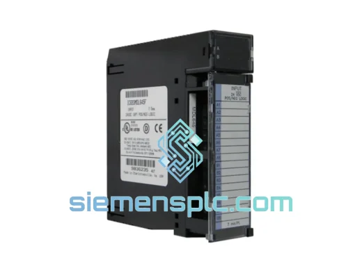
The IC693MDL940 occupies a single slot in any GE Series 90-30 rack and delivers 16 independently isolated relay contact outputs rated at 2 A continuous per point. Unlike transistor-output modules that are constrained to DC loads and a fixed polarity, the IC693MDL940’s dry-contact relay architecture allows each output to switch 120 VAC, 240 VAC, or 24 VDC loads from a single module without external interface relays. This characteristic makes it the default selection for motor-starter coil control, solenoid valve actuation, and pilot-light circuits where load voltage varies across the panel.
Within the Series 90-30 control loop, the module sits at the final execution boundary: the CPU asserts an output coil state in the %Q reference table, the backplane bus transfers that state to the module’s output latch on each I/O scan, and the relay contact closes or opens within the module’s specified operate time. The deterministic scan-to-contact latency is bounded by the CPU’s I/O scan period plus the relay operate time (≤10 ms typical), which is acceptable for all discrete actuator classes that do not require sub-millisecond switching.
The module’s relay contact isolation architecture separates the field-side wiring from the backplane logic bus at two levels: the coil drive circuit uses optical coupling between the backplane logic and the relay coil, and the relay contact itself provides galvanic isolation between the field load and all internal electronics. This two-stage isolation boundary limits the propagation of field-side transients—inductive kickback from contactor coils, capacitive coupling from long cable runs—into the CPU’s memory bus, which is a common root cause of spurious program faults in relay-heavy panels.
Each of the 16 output points is individually fused at the field wiring terminal, and the module provides per-point LED status indication that reflects the commanded state of the relay coil, not the contact continuity. Engineers should note this distinction: the LED confirms that the CPU has asserted the output, but does not confirm that the field-side load circuit is intact. For applications requiring contact-level diagnostics, a feedback input wired to an IC693MDL240 or equivalent discrete input module is the standard practice.
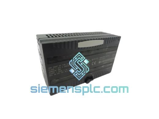
The IC693MDL940 is compatible with all Series 90-30 5-slot and 10-slot baseplate configurations, including the IC693CHS391, IC693CHS392, IC693CHS397, and IC693CHS398 racks. It is also supported in remote I/O expansion racks connected via the IC693BEM331 Bus Expansion Module. The module draws its logic power from the backplane’s 5 VDC rail (≤150 mA) and its relay coil power from the backplane’s 24 VDC rail (≤480 mA at full load, all 16 relays energized simultaneously). Panel designers must account for this coil current budget when sizing the rack power supply, particularly in high-density configurations where multiple relay output modules share a single IC693PWR321 or IC693PWR330 supply.
Relay contact life is rated at 100,000 electrical operations at rated resistive load (2 A, 240 VAC). For inductive loads—motor starters, solenoids—the effective contact life is reduced by the inrush and arc energy at contact break. Specifying a snubber network (RC or MOV) across the load terminals is standard practice to extend contact life and suppress radiated EMI at the switching instant. The module’s terminal block accepts 14–22 AWG field wiring, and the removable terminal block design allows pre-wired field connections to be transferred to a replacement module without rewiring.
Programming is handled through GE Proficy Machine Edition (v9.x and later) or the legacy Logicmaster 90-30 environment. The module is addressed as a standard discrete output block in the hardware configuration tree; no special function blocks or firmware downloads are required. The %Q reference address range assigned to the module is determined by its physical slot position in the rack, following the Series 90-30 automatic I/O addressing convention.
Real-time Stock & RFQ: [email protected] | WhatsApp: +86 18359268345
| Parameter | Value |
|---|---|
| Part Number | IC693MDL940 |
| Manufacturer | GE Fanuc / GE Automation & Controls |
| Platform | Series 90-30 PLC |
| Module Type | Discrete Output – Relay Contact |
| Output Points | 16 (individually isolated) |
| Output Current Rating | 2 A continuous per point |
| Output Voltage Range | 5–240 VAC / 5–30 VDC |
| Contact Configuration | SPST-NO (normally open) dry contact |
| Relay Operate Time | ≤10 ms typical |
| Relay Release Time | ≤10 ms typical |
| Electrical Contact Life | 100,000 operations at rated resistive load |
| Mechanical Contact Life | 10,000,000 operations |
| Backplane Logic Power | 5 VDC, ≤150 mA |
| Relay Coil Power | 24 VDC backplane, ≤480 mA (all 16 on) |
| Isolation (Field to Logic) | Optical + relay contact galvanic isolation |
| LED Indication | Per-point output status (coil state) |
| Terminal Block | Removable screw terminal, 14–22 AWG |
| Operating Temperature | 0°C to 60°C |
| Storage Temperature | -40°C to 85°C |
| Relative Humidity | 5–95% non-condensing |
| Form Factor | Single-slot, Series 90-30 standard |
| Certifications | UL Listed, CE Marked, CSA |
| Country of Origin | United States |
| Warranty | 12 months from date of shipment |
The IC693MDL940’s internal architecture is structured around three discrete functional layers that operate independently to ensure signal integrity and field-side fault containment.
Optical Isolation Stage: The backplane data bus drives a bank of 16 optocouplers, one per output channel. The optocoupler’s LED side is powered from the 5 VDC logic rail; the phototransistor side drives the relay coil circuit from the 24 VDC backplane rail. This arrangement means that a complete failure of the 24 VDC coil supply—whether from a blown fuse or supply fault—will de-energize all relay coils and open all contacts, placing the field loads in a known de-energized state. The logic bus remains unaffected, and the CPU can continue executing the control program and logging the fault condition.
Relay Contact Stage: Each relay is a sealed, bifurcated-contact design. Bifurcated contacts provide two parallel current paths per contact, which reduces the probability of a high-resistance contact failure caused by surface oxidation or contamination—a relevant consideration in environments with airborne particulates or humidity cycling. The relay coil incorporates a flyback diode across the coil terminals to suppress the inductive voltage spike at de-energization, protecting the optocoupler’s phototransistor from reverse-voltage stress.
EMC Design: The module’s PCB layout routes the 24 VDC coil drive traces with a ground plane return directly beneath them, minimizing the loop area of the coil current path and reducing radiated magnetic field emissions at the relay switching frequency. The field-side terminal block is physically separated from the logic PCB by a creepage and clearance distance compliant with IEC 60664-1 for 300 V rated insulation, which satisfies the requirements for 240 VAC field wiring without additional insulation barriers.
Thermal Management: At full load (16 relays energized, 2 A per contact), the module’s internal power dissipation is dominated by relay coil resistance losses (~30 mW per coil) and contact resistance losses (~20 mW per contact at 2 A). Total worst-case dissipation is approximately 800 mW, which is within the passive convection cooling capacity of the standard Series 90-30 rack without forced air. The module does not require a fan or heat sink under any rated operating condition.
Every IC693MDL940 unit dispatched from our Xiamen, China facility is sourced through verified industrial distribution channels with full traceability to the original GE Fanuc manufacturing lot. Pre-shipment inspection covers visual integrity of the module housing, label authenticity verification against GE’s published part marking standards, and a power-on functional check of relay coil energization for each output point where test fixtures permit.
Units are packed in anti-static bags with humidity indicator cards, placed in foam-lined cartons rated for international air freight handling. Export documentation—commercial invoice, packing list, and certificate of origin—is prepared to comply with customs requirements in the destination country. Xiamen’s port infrastructure supports direct air freight connections to major industrial hubs in Europe, Southeast Asia, the Middle East, and the Americas, with typical transit times of 3–7 business days for air express shipments. Sea freight consolidation is available for bulk orders where lead time permits. All shipments carry a 12-month warranty against manufacturing defects from the date of delivery.
Email: [email protected]
WhatsApp: +86 18359268345
Web: siemensplc.com
Location: Xiamen, China
© 2026 siemensplc.com. All rights reserved.
We check the full part number, brand, series and visible nameplate information before quotation.
Sales confirms stock path, condition option, quantity and realistic lead time for export dispatch.
DHL, FedEx, UPS or buyer courier arrangements can be reviewed with packing requirements.
Similar brand or category products for fast comparison and multi-item RFQ lists.